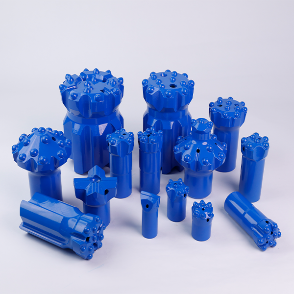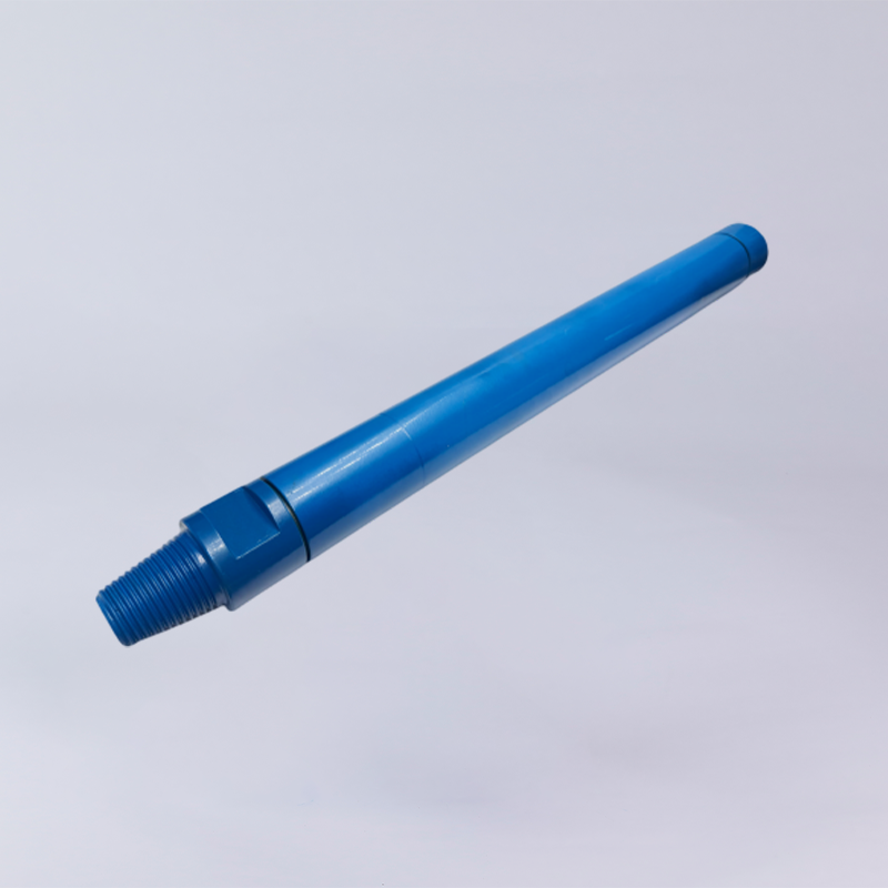
DTH drill bit buttons usually break, chip, or pop out because of excessive impact or feed force, blank firing, worn or improperly reground carbides, unsuitable carbide grade, or drilling with a damaged and worn-out bit. Repeated impact loading can create micro-cracks in the carbide or weaken the surrounding bit body. Once a button becomes flat, overheated, cracked, or poorly supported, continued drilling can lead to chipping, shearing, crushing, or complete button loss.
The four most common causes are:
- Excessive impact or feed force — overloads the carbide and bit face, increasing the risk of cracking or crushing.
- Blank firing or unstable rock contact — exposes the buttons to abnormal impact loads without proper support from the rock.
- Flat, worn, or improperly reground carbides — changes button geometry and contact stress, accelerating chipping and micro-cracking.
- Unsuitable carbide grade or drilling parameters — a poor match between carbide properties, rock conditions, rotation, feed, and percussion can cause premature wear or breakage.
What Happens When a DTH Drill Bit Button Fails?
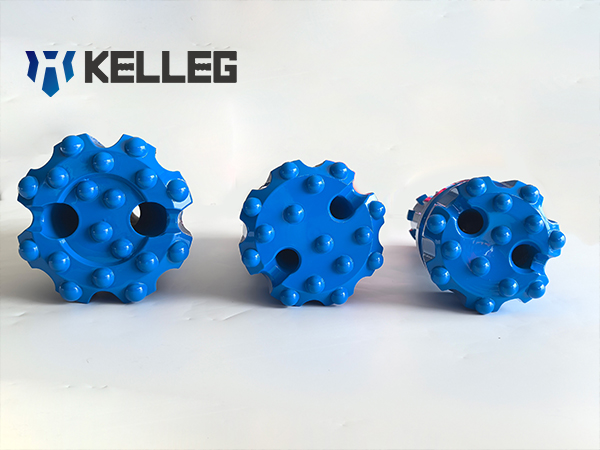
A DTH drill bit button rarely fails without warning. In many cases, the failure starts with a small crack, a worn or flattened carbide surface, excessive heat, or loss of support around the carbide socket. Repeated hammer impacts then turn that local damage into chipping, shearing, crushing, or complete button loss.
The important point is that the carbide button and the steel bit body work together. A button can only withstand repeated impact when it has adequate support from the surrounding bit body and stable contact with the rock.
Carbide Buttons Carry Repeated Impact Loads
Every hammer cycle transfers impact energy through the bit to the carbide buttons and then into the rock. The buttons are exposed to repeated compressive and shear stresses at the carbide-rock contact area.
Under normal drilling, the carbide penetrates the rock while the bit rotates and the flushing hole removes the cuttings. The loading is repeated thousands of times, so even a small defect can become significant over time.
A carbide button may begin to fail because of:
- a small crack or micro-crack;
- excessive wear or a flat contact surface;
- overheating;
- excessive feed force;
- unstable contact with the rock;
- damage from previous drilling or improper grinding.
Once the button is damaged, continued percussion can extend the crack or concentrate the load on a smaller contact area. The result may be carbide chipping, top shearing, crushing, or complete button loss.
This is why a bit that still appears usable can sometimes lose a button suddenly during the next drilling cycle.
The Bit Body Supports the Carbide
The carbide button is not working alone. It is held inside a precisely formed carbide socket in the steel bit body. The surrounding steel provides mechanical support and helps transfer the impact load into the bit face.
If the support around the button becomes damaged or excessively worn, the carbide is exposed to higher local stress. This can eventually cause the button to loosen or pop out.
Common warning signs include:
- cracks in the bit body near a carbide button;
- cracks originating from the bottom of the carbide socket;
- damaged or enlarged carbide sockets;
- intact carbide with the surrounding steel worn away; and
- excessive body wash around the carbide.
These failures should not automatically be blamed on poor carbide quality. The carbide-body interface, socket condition, grinding practice, drilling parameters, and rock conditions all need to be considered.
If a crack consistently develops around the carbide socket, particularly when the carbide itself remains intact, the bit should be removed from service and returned to the manufacturer for inspection and failure analysis. An abnormal carbide-to-socket interference condition, for example, cannot be reliably diagnosed by changing drilling parameters alone.
10 Common Causes of DTH Drill Bit Button Breakage
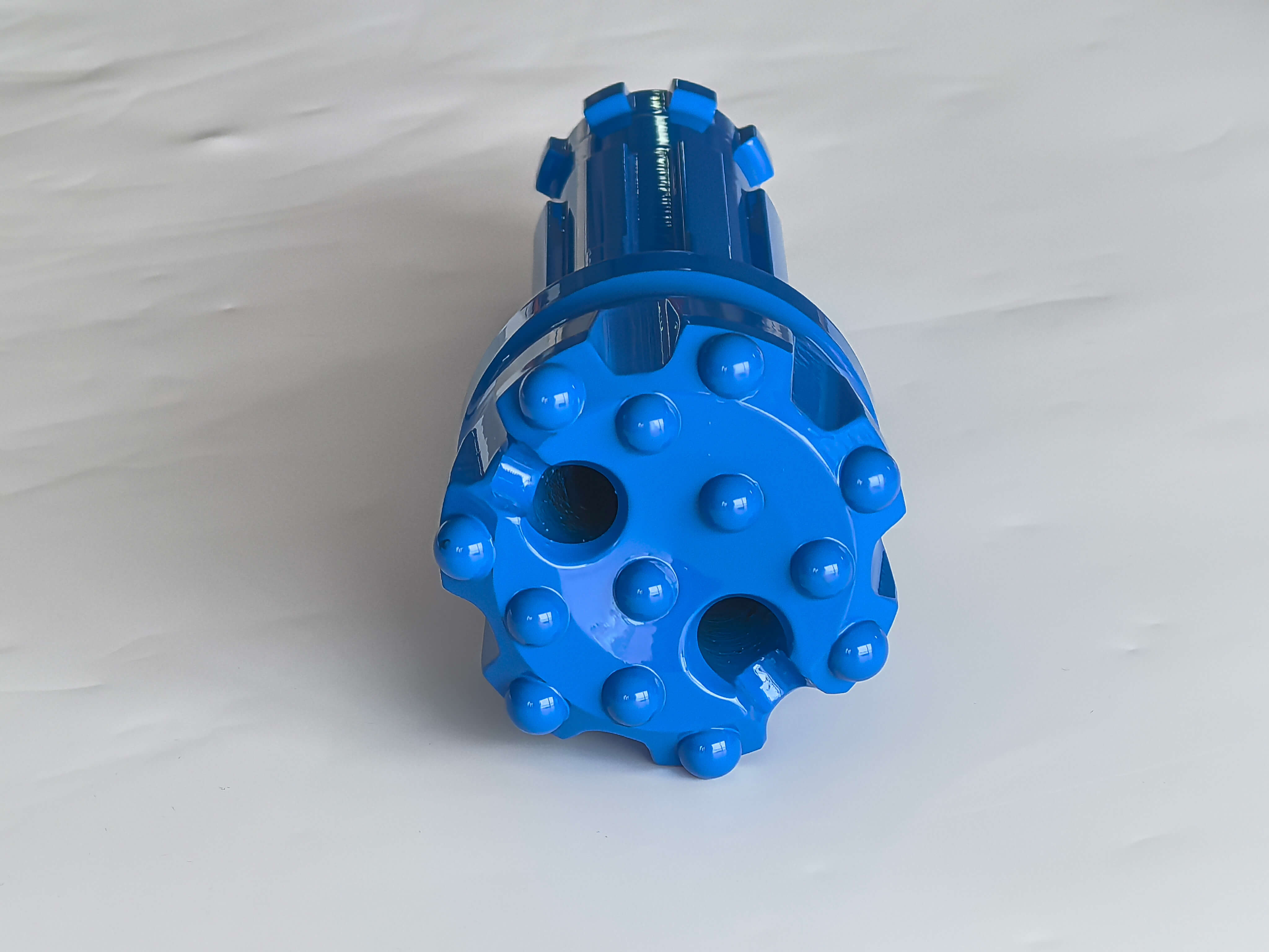
1. Blank Firing and Back Hammering
A DTH hammer should not start percussion until the bit is firmly seated against the rock. If the hammer fires while the bit is not fully supported by the rock, the carbide buttons can receive impact energy without the normal resistance of the formation.
This is commonly referred to as blank firing or dry firing. The sudden unsupported impact can create abnormal stress at the carbide-rock interface and around the carbide sockets.
Repeated or severe blank firing can contribute to:
- carbide cracking or chipping;
- cracks around the carbide socket;
- face cracking;
- damage to the bit body; and
- premature button loss.
Back hammering can create a similar problem when the bit loses stable contact with the bottom of the hole and the impact system continues to operate. This is particularly important in fractured, loose, or irregular formations where maintaining consistent bit contact can be difficult.
How to Prevent It
- Make sure the bit is fully seated on the rock before starting percussion.
- Avoid prolonged percussion when the bit is not cutting.
- In fractured or loose formations, reduce the risk of bit bouncing by adjusting feed and drilling parameters.
- Stop percussion when the bit loses effective contact with the rock.
Field check:
Does the hammer start percussion before the bit is fully seated on the rock?
If the answer is yes, correct the drilling procedure before changing the carbide grade or replacing the bit.
2. Excessive Feed Force
Feed pressure keeps the bit engaged with the rock, but excessive feed force can overload the carbide buttons and the bit face.
When the applied force exceeds what the rock and bit can accommodate, the buttons can experience excessive compressive loading and localized stress. This can lead to carbide crushing, button chipping, or cracking of the bit face.
One common failure pattern is a crack developing:
- between carbide buttons;
- between a carbide button and a flushing hole; or
- across the bit face.
Excessive feed force can also become more problematic when drilling fractured or obstructed ground. Instead of allowing the carbide to cut progressively into the formation, excessive loading can force the bit against an obstruction and increase the risk of button damage.
How to Prevent It
- Adjust feed force according to the rock condition and drilling response.
- Reduce feed force if the bit face begins to crack or the buttons show crushing.
- In deep holes, account for the additional load created by the weight of the drill pipe.
- When drilling through loose, fractured, or obstructed ground, avoid forcing the bit into the formation.
On some rigs, pull-back may be required in deep holes to compensate for excessive downward loading from the drill string.
The target is not maximum feed force. It is stable bit-rock engagement without excessive loading.
3. Insufficient Feed Pressure
Reducing feed force does not mean that lower is always better.
If feed pressure is too low, the bit may not remain firmly engaged with the rock. The bit can bounce or lose stable contact during percussion, producing unstable impact loading instead of efficient energy transfer into the formation.
This can contribute to:
- irregular carbide loading;
- button chipping;
- premature carbide wear;
- unstable penetration; and
- increased risk of impact damage.
The correct feed pressure therefore depends on the hammer, bit, rock formation, and drilling conditions.
The practical objective is:
Match feed pressure to the rock condition and maintain stable bit-rock contact.
Do not respond to button breakage by simply increasing or decreasing feed pressure. First inspect the failure pattern, drilling behavior, rock condition, and bit contact. The correct adjustment is the one that keeps the bit engaged without overloading the carbide.
Carbide Grinding and Regrinding Problems
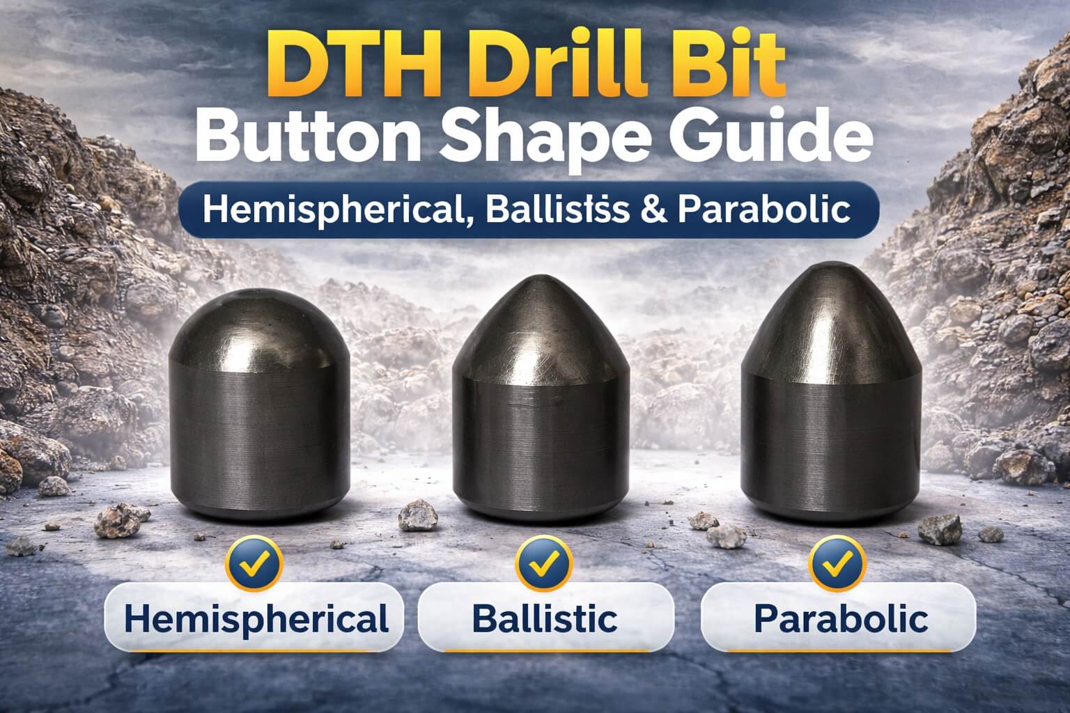
Carbide grinding is not just a maintenance task. It directly affects button geometry, penetration, heat generation and the amount of steel supporting each carbide.
A common mistake is to treat grinding as something that only needs to be done after a button becomes visibly damaged. In practice, both late grinding and excessive grinding can shorten DTH drill bit life.
4. Drilling With Flat Carbide Buttons
A carbide button is designed to maintain a specific working shape as it penetrates the rock. As the button wears, its contact area changes and the bit becomes less effective at penetrating the formation.
Once a button becomes significantly flat:
- penetration efficiency decreases;
- the contact area with the rock changes;
- higher force may be required to maintain penetration;
- heat generation can increase;
- localized stress can develop around the worn area; and
- the risk of carbide chipping, cracking, or crushing increases.
The problem becomes more serious when a flat button is kept in service for too long. Instead of maintaining an efficient cutting action, the worn carbide can transmit higher loads into the button and surrounding bit body.
This is why drilling with flat carbides is a common contributor to carbide failure and face cracking.
What to Do
Inspect the buttons regularly and regrind them before severe flattening develops. Follow the correct grinding procedure for the button geometry and avoid removing unnecessary steel from the bit face.
5. Grinding Too Late: Micro-Cracks Can Become Major Breakage
Carbide failure does not always begin with a visibly broken button.
In some formations, especially relatively non-abrasive rocks such as limestone, carbide buttons can develop a characteristic snake-skin wear pattern. The surface may appear worn rather than seriously damaged, but continued drilling can allow micro-cracks to develop.
If grinding is delayed, these small cracks can grow under repeated impact loading and eventually result in:
- carbide chipping;
- carbide cracking;
- crushed button tops;
- complete button failure.
This is why the correct regrinding interval depends on the wear pattern, not simply the number of meters drilled.
In non-abrasive rock, buttons may require more frequent inspection because they can become flat without the same level of self-sharpening that occurs in more abrasive formations.
Field Prevention
- Inspect carbide buttons frequently.
- Watch for flat spots and snake-skin wear patterns.
- Shorten the grinding interval when drilling in non-abrasive rock.
- Regrind when the carbide becomes dull, or micro-cracks begin to appear.
- Do not wait until the button is crushed or severely chipped.
A useful field rule is:
Grind to control wear before the carbide becomes structurally damaged—not after the button has already failed.
6. Excessive Grinding Can Damage the Bit Body
More grinding is not necessarily better.
The objective of carbide grinding is to restore the working geometry of the button while preserving sufficient steel around the carbide socket. If too much of the bit body is removed during sharpening, the carbide can become excessively exposed and lose part of its mechanical support.
This can lead to:
- reduced carbide support;
- excessive carbide protrusion;
- weakened areas around the socket;
- accelerated body wear;
- increased risk of carbide pop-out.
This is particularly important when operators repeatedly grind the bit face to compensate for worn or flat buttons. Removing excessive steel may make the carbide appear sharp again, but it can reduce the support that keeps the button securely seated.
As a general field guideline, carbide protrusion should not exceed approximately three-quarters of the carbide diameter after grinding. The exact acceptable geometry can vary with button design and bit manufacturer, so the manufacturer's grinding specifications should take priority.
The key principle is simple:
Restore the carbide shape without unnecessarily removing the steel that supports it.
Rock Conditions Can Cause Carbide Failure
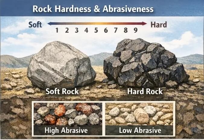
The same DTH drill bit can behave very differently in different formations. Rock abrasiveness affects not only how quickly the carbide wears, but also how much of the surrounding steel bit body is removed and how well the carbide remains supported.
This creates two different problems at opposite ends of the abrasiveness range: highly abrasive rock can wash away the bit body, while relatively non-abrasive rock can leave carbide buttons flat and prone to cracking.
7. Extremely Abrasive Rock Causes Body Wash and Carbide Exposure
In highly abrasive formations, the steel around the carbide buttons can wear rapidly. This condition is commonly referred to as body wash.
As the bit face and the steel surrounding the buttons wear away, the carbide can become increasingly exposed. The loss of steel support makes the buttons more vulnerable to impact damage and can eventually contribute to carbide pop-out.
Typical signs include:
- excessive steel wear across the bit face;
- pronounced wear around carbide buttons;
- enlarged or worn carbide sockets;
- excessive carbide exposure;
- premature loss of buttons despite otherwise acceptable carbide condition.
Poor flushing can make the problem worse. If rock cuttings are not removed efficiently, abrasive particles can remain around the bit face and increase wear.
How to Reduce Body Wash
The exact adjustment depends on the hammer, bit design, and formation, but field measures may include:
- reduce rotation speed where practical to produce larger cuttings that are easier to evacuate;
- maximize flushing within the equipment's operating limits;
- improve cuttings removal from the hole;
- use drilling foam where appropriate to help lift and transport cuttings;
- clean the hole regularly when conditions require it; and
- adjust the hammer choke or up-hole velocity where the drilling system allows this adjustment.
The objective is not simply to slow the bit down. It is to reduce unnecessary steel wear while maintaining effective rock-cutting and flushing performance.
8. Non-Abrasive Rock Can Also Damage Carbide
Low abrasiveness does not mean low risk of carbide failure.
In relatively non-abrasive formations such as limestone, the carbide may not wear in a way that continuously maintains an effective working profile. Instead, the button can gradually become flat and develop a characteristic snake-skin wear pattern.
If the bit continues drilling after the button has become dull, the worn carbide can experience less effective penetration and increasingly unfavorable loading. Repeated impact can then contribute to micro-cracking, chipping or crushing of the carbide.
Typical warning signs include:
- flat carbide buttons;
- snake-skin wear patterns;
- small surface cracks;
- reduced penetration;
- chipped or cracked button tops.
How to Prevent It
- Inspect carbide buttons more frequently in non-abrasive formations.
- Look for snake-skin wear and early micro-cracks.
- Shorten the regrinding interval when the buttons become dull quickly.
- Regrind before severe flattening or cracking develops.
- Select a carbide grade and button design appropriate for the actual rock condition.
Hard rock does not automatically mean that the hardest carbide is the best choice. Carbide selection involves a balance between hardness, wear resistance, and toughness, together with the impact conditions and abrasiveness of the formation.
The goal is to select a carbide that can resist wear without becoming unnecessarily susceptible to chipping or cracking under repeated impact.
Carbide Grade and Button Design Matter
Carbide failure is not always caused by poor drilling practice. The carbide itself also has to match the application.
DTH drill bit buttons are commonly made from tungsten carbide with a cobalt binder. By adjusting carbide grain structure, cobalt content and other material characteristics, manufacturers can produce grades with different combinations of hardness, wear resistance and toughness.
The correct grade is therefore not simply the hardest grade available. It must provide enough wear resistance for the formation while retaining sufficient toughness to withstand repeated impact.
9. Carbide Grade Too Hard for the Rock
A harder carbide grade can provide good wear resistance, which is useful in highly abrasive formations. However, selecting carbide based on hardness alone can create problems in applications where the buttons are exposed to severe impact, interrupted cutting or rapidly changing rock conditions.
In general, increasing hardness and wear resistance can involve a trade-off with fracture toughness, depending on the carbide composition and microstructure.
A grade that is too hard or insufficiently tough for a high-impact application may be more susceptible to:
- carbide chipping;
- edge cracking;
- button cracking;
- impact-related fracture; and
- premature carbide loss.
This does not mean that a softer carbide is always better. In highly abrasive rock, insufficient wear resistance can cause rapid button wear, excessive flattening, and more frequent grinding.
The practical question is therefore not:
“What is the hardest carbide grade?”
It is:
“Which carbide grade provides the right balance of wear resistance and toughness for this drilling condition?”
When selecting a grade, consider:
- rock hardness;
- rock abrasiveness;
- degree of fracturing;
- percussion energy;
- drilling stability;
- expected bit life;
- frequency and severity of impact loading.
If carbide buttons are repeatedly cracking or chipping while the drilling parameters are within the normal operating range, the carbide grade should be reviewed together with the button geometry and rock conditions.
10. Wrong Button Geometry or Protrusion
Carbide grade is only one part of the equation. Button geometry and placement also determine how impact energy is transferred into the rock.
The relevant factors can include:
- button shape;
- button diameter;
- carbide protrusion;
- button position on the bit face;
- spacing between buttons;
- flushing-hole and button layout.
Different button profiles, such as domed, ballistic, or parabolic designs, can produce different penetration, wear, and stress behavior. The appropriate geometry depends on the bit design, hole diameter, hammer performance, and formation.
Button protrusion also matters. Excessive protrusion can leave the carbide with insufficient support from the surrounding bit body, increasing its exposure to impact and bending loads. Insufficient protrusion, on the other hand, can reduce effective penetration as the bit face wears.
The correct geometry is therefore a balance between penetration, wear resistance, carbide support, and impact loading.
Button geometry must match the drilling application, not just the nominal hole diameter.
For example, two DTH bits with the same hole diameter can require different button configurations when used in different formations or with different drilling conditions.
When specifying a replacement DTH bit, provide more than the hole diameter. Useful information includes:
- hole diameter;
- hammer model;
- rock type and abrasiveness;
- drilling depth;
- typical drilling parameters;
- current button failure or wear pattern;
- approximate meters drilled per bit.
This information allows the bit configuration and carbide selection to be evaluated together rather than treating button breakage as a single-component problem.
DTH Drill Bit Button Failure Diagnostic & Prevention Matrix
When a DTH drill bit starts losing buttons, the failure pattern can often point to the underlying cause. Do not inspect the broken carbide alone. Check the button shape, socket condition, surrounding bit body, face wear, flushing holes, and drilling conditions together.
| Failure Pattern | Likely Root Cause | What to Check | Field Prevention |
|---|---|---|---|
| Carbide chipped | Over-drilling, flat carbide, unsuitable carbide grade | Button shape, wear pattern, grinding interval | Regrind before severe wear; select a suitable carbide grade |
| Carbide cracked | Impact shock, micro-cracking, unsuitable carbide grade | Crack direction, rock condition, button condition | Prevent blank firing; maintain stable bit-rock contact; review drilling parameters |
| Carbide completely missing | Over drilling, severe carbide damage, continued use of a damaged bit | Socket and surrounding bit body | Stop using severely damaged bits; inspect and replace when necessary |
| Carbide pop-out | Poor carbide support, excessive body wear, abnormal carbide-to-socket interference | Socket condition, body wash, carbide fit and support | Replace worn bits; inspect the socket and surrounding bit body |
| Top of carbide sheared | Overheating, flat carbide, forceful rotation against an obstruction | Button top, wear condition, rotation and loading conditions | Regrind worn carbides correctly; avoid excessive rotation or loading against obstacles |
| Carbide crushed into the bit body | Excessive loading, excessive carbide protrusion, prolonged drilling in non-abrasive rock | Button height, protrusion, and wear pattern | Shorten grinding intervals; restore proper button geometry before severe wear |
| Face crack | Excessive feed force or unstable loading | Crack location around carbides and flushing holes | Reduce excessive feed force and maintain stable bit engagement |
| Crack around carbide socket | Abnormal carbide-to-socket interference or localized body stress | Socket condition, surrounding bit body and crack location | Remove the bit from service and return abnormal bits to the manufacturer for inspection |
| Snake-skin wear | Non-abrasive rock, late grinding | Carbide surface and wear pattern | Inspect more frequently and regrind before severe flattening or micro-cracking |
| Excessive body wash | Highly abrasive rock, inadequate flushing or unsuitable drilling conditions | Steel wear around carbides, face condition and flushing performance | Improve flushing; optimize rotation and cuttings removal; replace excessively worn bits |
The failure pattern is often more useful than the broken button itself. Inspect the carbide, socket, bit face, and wear pattern together before changing drilling parameters.
How to Prevent DTH Drill Bit Button Breakage in the Field
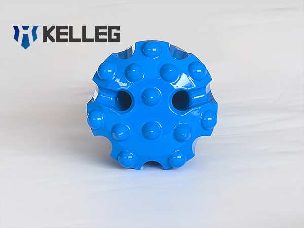
Preventing carbide button failure is not simply a matter of choosing a stronger carbide grade. Bit life depends on how percussion, feed, rotation, flushing, and bit condition work together during drilling.
The practical objective is to keep the bit cutting efficiently while avoiding unstable impact, excessive loading, and unnecessary wear on the bit face.
Match Percussion, Feed and Rotation
Percussion energy, feed pressure, and rotation speed should be adjusted as a combination rather than treated as three independent settings.
Stable bit-rock contact + appropriate feed + controlled rotation = lower carbide stress.
Percussion provides the impact energy needed to break the rock. Feed pressure keeps the bit engaged with the formation, while rotation moves the buttons onto fresh rock and distributes wear across the bit face. If one parameter is poorly matched to the others, carbide loading can become uneven.
For example:
- Excessive percussion or feed can overload the buttons and increase the risk of cracking, crushing and face damage.
- Insufficient feed can allow the bit to bounce or lose stable contact, increasing abnormal impact loading.
- Excessive rotation can increase wear on the carbide and bit face, particularly when the formation is highly abrasive.
- Insufficient rotation can cause uneven button loading and localized wear in some drilling conditions.
The correct combination depends on the hammer, bit design, hole diameter, rock hardness and abrasiveness, and ground stability. When a bit begins losing buttons, do not simply increase or reduce one parameter. First examine the failure pattern and determine whether the bit is maintaining stable contact with the rock.
Control Flushing and Cuttings Removal
Flushing is part of bit protection, not just a way to remove cuttings from the hole.
Adequate flushing flow and pressure help carry broken rock away from the bit face. When cuttings remain around the face or repeatedly circulate through the cutting zone, they can increase abrasive wear on the carbide and the surrounding bit body. Poor cuttings removal can also contribute to excessive body wash and reduce the support around carbide buttons.
Pay attention to:
- Flushing pressure and flow — sufficient to remove cuttings under the actual hole conditions.
- Cuttings evacuation — avoid allowing broken rock to accumulate around the bit face.
- Hole cleaning — particularly important in deep, fractured or unstable formations.
- Body wash — monitor steel wear around the buttons and flushing holes.
- Regrinding frequency — increase inspection and grinding frequency when poor flushing or severe abrasive wear is shortening button life.
Poor flushing does not only slow drilling. Repeated recirculation of cuttings can accelerate wear on both the bit face and surrounding bit body.
In highly abrasive formations, practical measures may include improving flushing, using drilling foam where appropriate, cleaning the hole regularly, and adjusting the hammer or air-flow configuration to improve cuttings removal. Rotation can also be reduced where practical if doing so produces larger cuttings and reduces unnecessary abrasive wear.
The objective is not simply to use more flushing. It is to maintain effective cuttings removal without creating unnecessary wear or unstable drilling conditions.
Stop Using a Bit After Major Carbide Damage
A DTH bit should not be kept in service simply because some carbide buttons are still intact.
If the bit has already developed multiple missing buttons, severely cracked carbides, a badly damaged face, or excessive body wash, continued drilling can turn a localized failure into broader bit damage.
The sequence can become:
Damaged bit → secondary damage → more carbide loss → increased body wear → higher cost per meter
A missing button also changes the load distribution across the remaining buttons. Continued drilling with a severely damaged bit can therefore accelerate wear on the surrounding carbides and bit face.
Before returning a worn bit to service, inspect:
- Number and location of missing or damaged buttons
- Carbide cracks and chips
- Button height and wear profile
- Condition of carbide sockets
- Face cracks
- Steel wear around the buttons
- Flushing-hole condition
- Overall body wash
Minor wear can often be managed through timely regrinding. Major carbide loss, severe face cracking, damaged sockets, or excessive body wash are different situations. At that point, replacing the bit is generally more appropriate than trying to recover additional meters from a structurally damaged tool.
The goal is not to get the maximum number of meters from one bit at any cost. The goal is to achieve consistent drilling performance at a controlled cost per meter.
DTH Drill Bit Regrinding SOP: Field Checklist
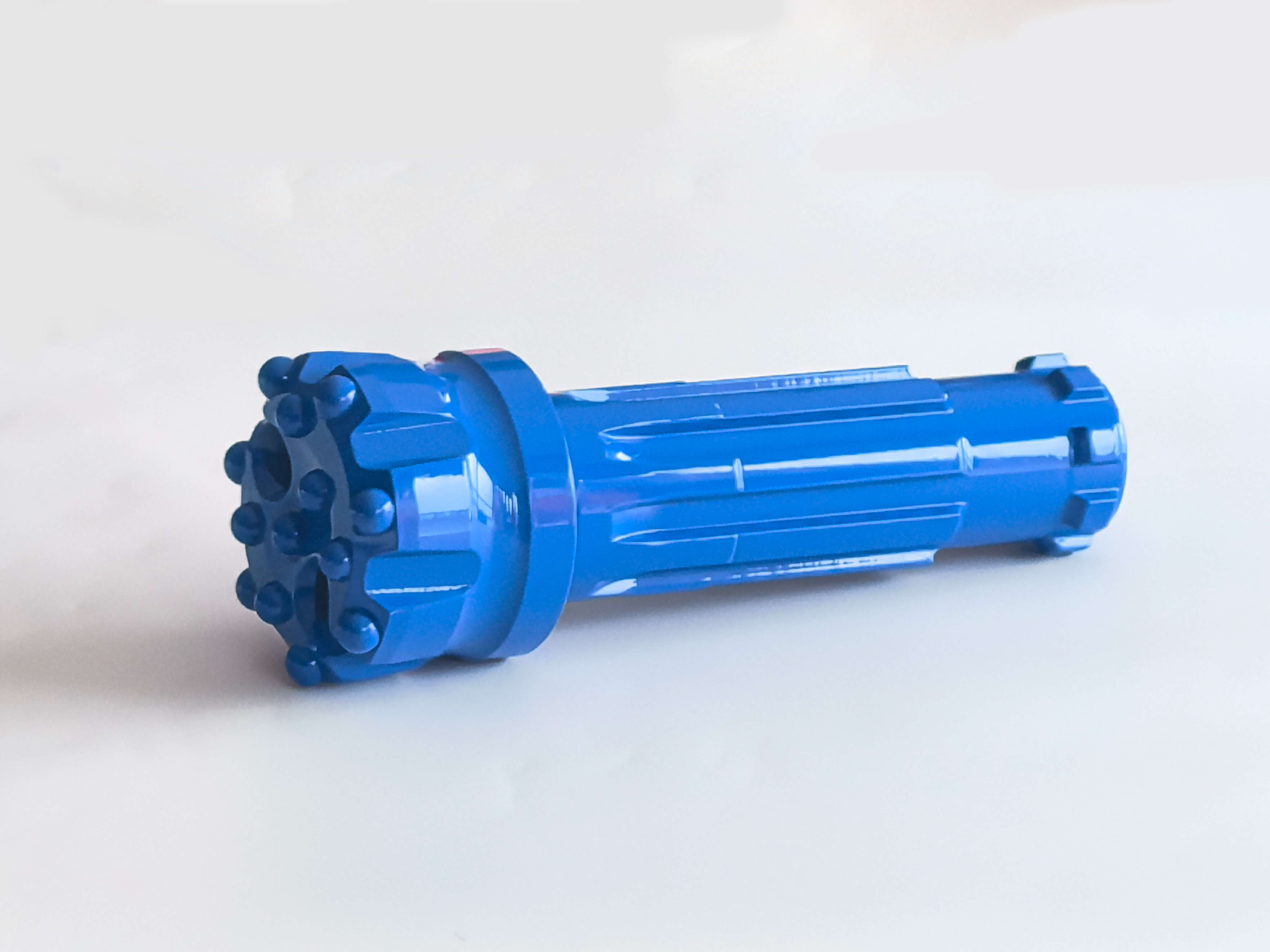
Regular inspection and timely regrinding can prevent minor carbide wear from developing into major button failure. The purpose of regrinding is to restore an effective carbide profile while maintaining adequate support from the surrounding bit body.
Use the following field checklist before, during, and after each drilling cycle.
Before Drilling
Before putting a DTH drill bit back into the hole, inspect the carbide and bit body rather than checking only the overall appearance.
- Check carbide buttons for cracks or visible damage
- Check button protrusion and overall carbide height
- Check for flat, dull, or heavily worn carbides
- Inspect flushing holes for blockage or damage
- Check the bit face and surrounding bit body for excessive wear
- Confirm that the bit design and carbide grade are suitable for the rock condition
- Confirm the hammer, bit diameter, and bit configuration are correctly matched
A bit with significant carbide damage should not be returned to service simply because most of the buttons are still intact. Check the wear pattern and structural condition before deciding whether to regrind or replace it.
During Drilling
The way the bit behaves in the hole can provide early warning of carbide problems.
- Maintain stable bit-rock contact
- Avoid blank firing and back hammering
- Monitor feed pressure and avoid excessive loading
- Avoid unnecessarily aggressive rotation
- Watch for changes in penetration rate
- Monitor flushing flow, pressure, and cuttings removal
- Check for abnormal vibration or unstable drilling
A sudden change in penetration, vibration, or flushing performance can indicate that the bit is no longer cutting normally. Do not wait for a button to break before inspecting the bit.
After Each Hole / Drilling Cycle
Inspect the bit while the wear pattern is still easy to identify.
- Inspect the carbide wear pattern
- Look for snake-skin wear
- Check for micro-cracks or early surface cracking
- Check for missing, chipped, or crushed buttons
- Inspect body wash around the carbide buttons
- Check the condition of carbide sockets
- Record drilling meters or holes completed
- Decide whether regrinding is required before the next hole
Recording drilling meters together with the actual wear pattern is more useful than using a fixed grinding interval for every formation. A bit drilling limestone, highly abrasive rock, and fractured ground may develop very different wear patterns over the same number of meters.
When to Regrind
Regrinding should be performed while the carbide is worn but still structurally sound.
Regrind when:
- Carbide becomes noticeably flat
- Micro-cracks start appearing
- Snake-skin wear is developing
- Penetration rate begins to decline
- Button geometry is no longer being maintained
- Wear is changing the intended contact profile of the carbide
The correct grinding interval depends on the carbide grade, button design, rock abrasiveness, drilling parameters, and actual wear pattern. Non-abrasive formations may require more frequent inspection because carbide buttons can become flat without the same level of abrasive wear seen in highly abrasive rock.
Do not wait until:
- Carbide is crushed into the bit body
- Multiple buttons are missing
- Carbide sockets are visibly damaged
- Severe cracks have developed across the bit face
- The surrounding bit body has been excessively worn away
The practical rule is simple: regrind before wear becomes structural damage.
When to Discard the Bit
Regrinding cannot recover every damaged bit. Replace the bit when the surrounding steel or carbide sockets can no longer provide reliable support for the buttons.
Typical replacement conditions include:
- Excessive body wash
- Multiple missing buttons
- Damaged or enlarged carbide sockets
- Severe face cracking
- Excessive carbide exposure caused by body wear or over-grinding
- Significant structural damage to the bit body
Continuing to drill with a structurally damaged bit can increase the load on the remaining carbides and accelerate secondary damage. The additional meters gained may therefore cost more than replacing the bit earlier.
Regrind or Replace?
Regrind: Carbide is worn or flattened, but the button and socket remain structurally sound.
Inspect closely: Micro-cracks, snake-skin wear, unusual button protrusion or localized body wear are developing.
Replace: Multiple buttons are missing, sockets are damaged, the face is severely cracked, or body wash has significantly reduced carbide support.
Field rule: Regrinding is for controlling wear. It is not a method for recovering a structurally damaged DTH drill bit.
How Button Breakage Affects Cost per Meter
Carbide button failure affects more than DTH drill bit life. It can increase the total cost of drilling by reducing usable meters, increasing bit changes, and creating additional downtime.
A simple way to calculate the basic bit cost per meter is:
Bit cost per meter = DTH bit cost ÷ Drilled meters
For example, a $200 bit that drills 1,000 meters has a basic bit cost of $0.20 per meter. If premature button failure limits the same bit to 600 meters, the bit cost rises to approximately $0.33 per meter.
However, the actual drilling cost can be higher because bit replacement involves more than the purchase price.
Consider:
- Bit replacement time — time required to pull out and replace the bit
- Drilling downtime — lost production while the bit is being changed
- Labor — operator and maintenance time
- Machine idle time — equipment remains unavailable during an unplanned change
- Lost production — fewer drilled meters per shift
- Hammer or component damage — severe bit failure can create additional maintenance costs
- Regrinding cost — labor, equipment and consumables required to recover worn carbides
This is why a cheaper DTH bit is not necessarily cheaper per meter. If premature button failure reduces usable drilling meters or causes unplanned bit changes, the effective drilling cost can increase.
For drilling contractors, a more useful comparison is not simply price per bit, but:
Bit cost + maintenance + replacement downtime + related operating cost ÷ usable drilled meters
Tracking drilled meters, regrinding frequency, failure patterns, and replacement time gives a much clearer picture of actual DTH bit performance.
When Should You Change the DTH Drill Bit?
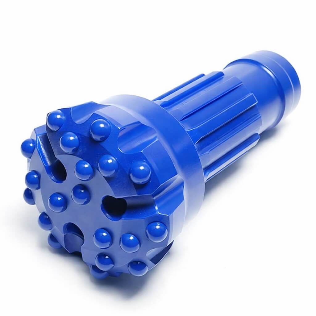
There is no single meter count that applies to every DTH drill bit. The correct replacement point depends on carbide wear, bit-body condition, rock formation, and drilling performance.
Should I keep drilling with one missing carbide button?
Not if the missing button is accompanied by significant damage to the surrounding bit face or socket.
One missing button does not automatically mean that every bit must be discarded immediately. However, continued drilling should only be considered after inspecting the socket, surrounding steel, remaining carbides, and overall wear pattern.
If multiple buttons are missing, the socket is damaged, or the bit face is severely worn or cracked, continuing to drill can accelerate secondary damage.
Can a flat carbide button cause other buttons to break?
Yes. A heavily flattened button can change the intended contact area and loading pattern of the bit face. Penetration may decrease, while the load on individual buttons can increase.
Continued drilling with severely worn carbides can therefore contribute to chipping, cracking, crushing, and uneven wear of other buttons.
Timely regrinding helps restore the intended carbide profile before excessive wear changes the way the bit loads the rock.
How often should DTH drill bits be reground?
There is no universal “X meters per regrind” rule.
Regrinding intervals depend on rock abrasiveness, drilling parameters, button geometry, and observed wear—not simply drilled meters.
In relatively non-abrasive formations, buttons may become flat or develop snake-skin wear sooner than expected. In highly abrasive formations, the surrounding bit body may wear rapidly and change carbide support.
The better approach is to inspect the actual wear pattern and establish a regrinding interval based on field performance.
Why do DTH buttons break in limestone?
Limestone is often less abrasive than many hard abrasive formations, but this does not mean carbide buttons are protected from failure.
Buttons can become flat, develop snake-skin wear, or develop micro-cracks when drilling continues after the effective carbide profile has been lost. If the bit is not reground at the appropriate interval, continued impact can lead to chipping, cracking, or crushing.
The key issue is not simply limestone hardness. Check carbide wear, button geometry, grinding interval, and drilling parameters together.
Why do DTH drill bits lose buttons in fractured rock?
Fractured or broken ground can make it difficult to maintain stable bit-rock contact. The bit may bounce, encounter irregular support, or strike loose material and obstructions.
This can create abnormal impact loading and increase the risk of carbide cracking, chipping, or pop-out.
In fractured formations, pay particular attention to feed control, stable bit engagement, flushing and blank-firing prevention. Do not force the bit against an obstruction simply to maintain penetration.
Does higher carbide hardness always mean longer bit life?
No.
Carbide selection involves a balance between hardness, wear resistance, and toughness. A grade with high wear resistance may perform well in abrasive rock, but carbide that is not sufficiently tough for the impact conditions may be more susceptible to chipping or fracture.
The appropriate grade depends on rock abrasiveness, impact severity, drilling stability, button design, and operating conditions.
The better question is not “What is the hardest carbide?” but:
“Which carbide grade provides the right balance of wear resistance and toughness for this drilling condition?”
What should I check when a new DTH bit loses buttons quickly?
Do not assume that the carbide grade is the only problem.
Check the following in order:
- Hammer and bit configuration — confirm the bit matches the hammer and hole diameter.
- Bit-rock contact — check for blank firing, bouncing or unstable engagement.
- Feed pressure — excessive or insufficient feed can both contribute to abnormal carbide loading.
- Rotation speed — check whether rotation is appropriate for the formation and bit design.
- Flushing — confirm that cuttings are being removed effectively.
- Button geometry — inspect button shape, height, protrusion, and face layout.
- Carbide grade — confirm that hardness, wear resistance, and toughness are suitable for the formation.
- Grinding practice — check whether the bit was reground correctly and at the appropriate interval.
- Failure pattern — compare the location and type of carbide damage with previous bits.
If a new batch repeatedly shows the same socket cracking, carbide fit problem, or abnormal body damage under normal drilling conditions, provide the manufacturer with photographs and failure details for further analysis.
How to Choose a DTH Drill Bit for Your Rock Conditions
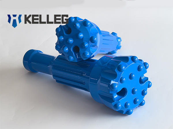
The correct DTH bit is not selected by hole diameter alone.
A practical selection sequence is:
Rock condition → Hole diameter → Hammer model → Button geometry → Carbide grade → Drilling parameters
Start with the formation. Rock hardness and abrasiveness influence carbide wear, while fractured or unstable ground changes the impact conditions at the bit face.
Then confirm the hole diameter and hammer model so that the bit is mechanically compatible with the drilling system.
After that, select the button geometry and carbide grade according to the expected wear and impact conditions. Button shape, protrusion, face layout, and carbide properties all affect penetration, wear, and button support.
Finally, match the bit to the actual percussion, feed, rotation, and flushing conditions used on the rig.
When selecting a replacement DTH bit, useful information for the supplier includes:
- Hole diameter
- DTH hammer model
- Rock type and abrasiveness
- Drilling depth
- Current button shape and configuration
- Typical drilling parameters
- Current bit life in meters
- Photos of the bit face and failed carbides
This information allows the bit configuration to be evaluated based on the actual drilling application rather than hole diameter alone.